30.  Flight Planning
The flight planning Dock Window contains the four tabs: Flight Plan, Flight Plan Remarks,
Fuel Report ( Aircraft Performance) and Current Performance (Aircraft Performance Collection).
See chapter Flight Plan Calculation for more information about automatic calculation of flight plans.
30.1. Flight Plans
Little Navmap allows to build flight plans or flight plan snippets using arbitrary start positions by using Append Position to Flight Plan or Add Position to Flight Plan in the map and other context menus.
Note that not all simulators or add-ons support this kind of flight plans.
You need to have the GLOBE elevation data installed to get the correct altitudes for arbitrary start or departure points. See Install GLOBE elevation data for installation instructions.
30.2. Header
The top shows a label that contains departure, departure position (parking, runway or helipad), destination, flight plan distance, traveling time, used procedures (SID, STAR, approach and transitions) as well as flight plan type and more.
The label also displays red error messages if, for example, the runway of a STAR differs from the runway of the following approach procedure.
Traveling time is only shown if a valid aircraft performance profile is loaded that has at least climb, cruise and descent speeds set.
The ARINC name of the approach procedure which is needed by some FMCs is shown in parentheses.
The header can be customized using Flight Plan Table Display Options.
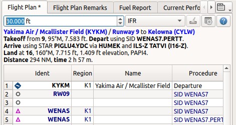
Header of a flight plan with all labels enabled.
30.3. Flight Plan Table
The table view allows the same operations as the search table view except sorting. See Tables for more information.
All selected elements in the flight plan table view will be highlighted
on the map using a black/green circle. See
Highlights for more information. Use
Shift+Click or Ctrl+Click to select two or more elements
(multi-selection).
The active flight plan leg is highlighted in magenta when Little Navmap is connected to a simulator, the user aircraft is airborne and user aircraft is closer than 40 NM to the flight plan.
Procedure legs have dark blue color and legs of a missed approach have a dark red color.
Alternate airports are shown at the end of the list using gray text. Note that more than one alternate can be added to the flight plan. Legs to the alternate airports originate all from the destination.
30.3.1.  Flight Plan Table Display Options
Choose Flight Plan Table Display Options from the flight plan table context
menu to customize the table columns, header and footer line content.
The changes to the table can be undone by selecting Reset View in the context menu.
The dialog uses a tree. See Trees for more information about this type of input element.
Same as main menu Tools -> Flight Plan Table Display Options.
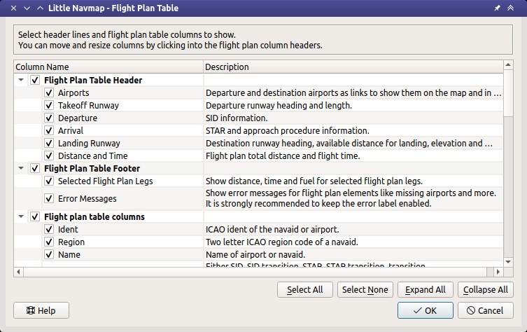
The flight plan display options dialog window.
30.3.2. Table Columns
Hovering the mouse over the table header shows more information about the columns in a tooltip.
Ident: ICAO ident of the navaid or airport. The ident can be suffixed as shown below:+or-and a distance value: Shows fixes in procedures that are relative to a navaid or waypoint plus the distance in NM to the waypoint.(IAF): Initial fix of a procedure or transition.(FAF): Final approach fix. Depending on procedure either the FAF or FACF are shown with a Maltese cross on the map and in the elevation profile.(FACF): Final approach course fix.(MAP): Missed approach point.
Region: Two letter region code of a navaid.Name: Name of airport or radio navaid if available.Procedure: EitherSID,SID Transition,STAR,STAR Transition,Transition,ApproachorMissedplus the name of the procedure. Contains the textAlternatefor alternate airports at the end of the list orDepartureorDestination.Airway or Procedure: Contains the airway name for en-route legs or procedure instructions. This field also shows track names if NAT, PACOTS or AUSOTS tracks are used. Airways are suffixed with the airway type likeN601 / V:VVictor or low altitude airwayJJet or high altitude airwayBBoth
Restriction:For airways:
Example
10,000: Minimum altitude for airway segment.Example
0-20,000: Maximum airway altitude. Minimum does not apply.Example
10,000-20,000: Minimum and maximum airway altitude.
For procedures: Altitude restriction or speed limit. A
/separates altitude and speed restriction. The following altitude restrictions exist for procedures:Number only: Fly at altitude or speed. Example:
5,400or210.Prefix
A: Fly at or above altitude or speed. Example:A 1,800.Prefix
B: Fly at or below altitude or speed. Example:B 10,000orB 220.Range: Fly at or above altitude one and at or below altitude two. Example:
A 8,000, B 10,000.Altitude and speed limit: Values separated by
/. Example:A 8,000, B 10,000/B220.Speed limit only: Speed restriction. Example:
B 250.Required vertical path angle: Example:
-3.1°.
Type: Type of a radio navaid. ShowsILSorLOCfor ILS or localizer approaches on the last runway leg.Freq.: Frequency or channel of a radio navaid. Also shows ILS or localizer frequency for corresponding approaches on the last runway leg.Range: Range of a radio navaid if available.Course °M: This is the start course of the great circle route connecting the two waypoints of the leg. Use this course at departure if you travel long distances without navaids. Be aware that you have to change you course constantly when traveling along a great circle line. See also Magnetic Declination for more information.Course °T: The same as the field above but using true course. Use this in areas with high magnetic declination.Distance: Distance of the flight plan leg.Remaining: Remaining distance to destination airport or procedure end point (usually the runway).Leg Time: Flying time for this leg. Calculated based on the selected aircraft performance profile (see Aircraft Performance). This is a static value and not updated while flying. Empty if performance calculation failed.ETA: Estimated time of arrival. This is a static value and not updated while flying. Calculated based on the selected aircraft performance profile. Empty if performance calculation failed.Fuel Rem.: Fuel remaining at waypoint, once for volume and once for weight. This is a static value and not updated while flying. Calculated based on the selected aircraft performance profile. Empty if aircraft performance profile has no fuel consumption numbers set.Wind: Magnetic wind direction and speed at the waypoint.Head- or Tailwind: Wind at waypoint. Headwind is indicated by arrow down▼and tailwind by an up arrow▲.Altitude: Calculated altitude at waypoint. Uses aircraft performance to determine altitude.Leg Safe Alt.: Leg safe altitude. Same as in Elevation Profile.LatitudeandLongitude: Coordinates in selected format from options on page Units.Related Ident/Freq./Dist./Bearing: Related navaid needed for procedures. Shows ident, frequency, distance and bearing as radial.Remarks: Turn instructions, flyover or related navaid for procedure legs. Also shows user remarks that can be edited with Edit Flight Plan Position or Edit Flight Plan Position Remarks. See Map Flight Plan Editing for more information.
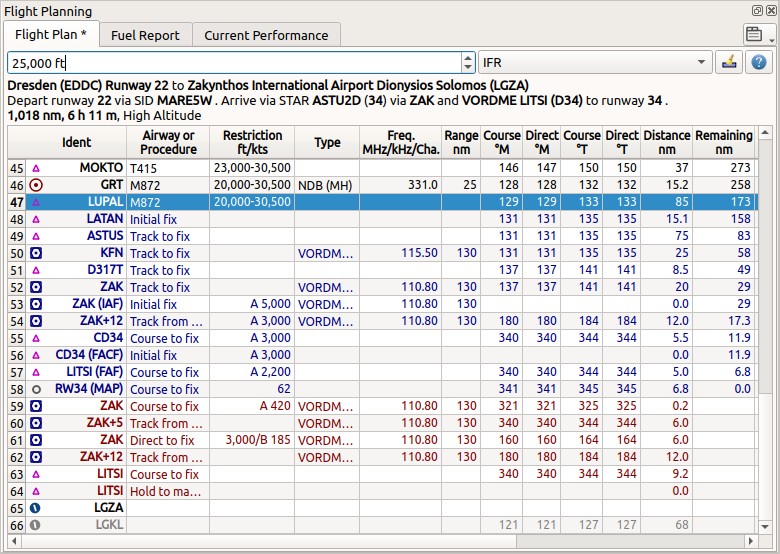
The Flight Planning dock window. The flight
plan uses a SID for departure and a STAR, a transition and an approach for arrival. Click image to enlarge.
Note
The flight plan table is static and does not update except when changing wind or aircraft performance. Look at the tab Tab Progress to see current information.
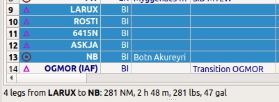
30.4. Selected Flight Plan Legs Footer
This footer line shows information about the selected flight plan legs.
Number of selected legs.
From and to waypoint.
Distance between the two waypoints.
Flight time based on currect aircraft performance configuration file.
Fuel required in weight and volume units.
Selected legs and information about the selected.
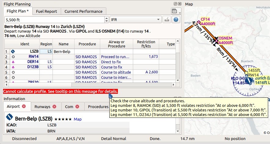
30.5. Error Messages Footer
If a waypoint of a flight plan cannot be found in the database it will be shown in red color. This can happen if the used AIRAC cycles do no match or old flight plan are loaded. The same applies to airways. The position on the map is still correct.
Airways are also displayed in red if the minimum altitude, maximum altitude or one-way restrictions are violated.
Hover the mouse over a field in the table to see a tooltip giving more information about the error.
You can also click on the red error message to see all errors found in the flight plan.
See also Warning and Error Messages.
Warning
Note that flight plans with errors are still usable in Little Navmap although saving and exporting to other formats is limited and can lead to unexpected results.
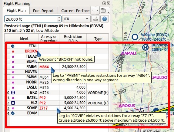
The Flight Planning with three different tooltips showing errors.
Tooltip on error message showing violations of altitude restrictions.
30.6. Mouse Clicks
A double-click on an entry in the table view shows either the airport
diagram or zooms to the navaid. Additionally, details are shown in the
Information dock window as well. A single click selects an object and
highlights it on the map using a black/green circle.
30.7. Top Buttons and Input Fields
30.7.1. Cruise altitude
This value is saved with the flight plan.
Changing this field updates the cruise altitude in the window Flight Plan Calculation.
Changing the cruise altitude of a flight plan using airways might result in errors (Error Messages Footer). This can happen if the cruise altitude violates airway altitude restrictions. Calculate the flight plan again to remove the errors.
Setting a too low cruise altitude might also violate procedure restrictions. See Altitude and Speed Restrictions.
Note
Note that Little Navmap does not support step climb or different altitudes for each waypoint.
30.7.2. Flight Plan Type
Either IFR or VFR.
This is saved with the flight plan and is only relevant for FSX, Prepar3D or MSFS.
Note
Note that the VFR/IFR selection affects flight plan loading in MSFS. You cannot load a VFR flight plan in MSFS which uses procedures, for example.
30.7.3.  Clear Selection
Deselect all entries in the table and remove any highlight circles from the map.
30.7.4.  Flight Plan Table Display Options
See chapter Flight Plan Table Display Options below.
30.8. Context Menu Flight Plan
30.8.1.  Show Information
Same as Show Information in the map context menu.
30.8.2.  Show on Map
Show either the airport diagram or zooms to the navaid on the map. The
zoom distance can be changed in the dialog Options on the tab
Map Navigation.
30.8.3.  Set Departure Runway
Same as Set Departure Runway in the map context menu.
30.8.4.  Set Destination Runway
Same as Set Destination Runway in the map context menu.
30.8.5.  Show Procedures
Same as Show Procedures in the map context menu. Only enabled for airports having procedures.
30.8.6.  Activate Flight Plan Leg
Makes the selected leg the active (magenta) flight plan leg. The active leg might change if Little Navmap is connected to the simulator and the user aircraft is moving.
You have to activate the leg manually if you would like to fly to an alternate airport.
Legs of a missed approach procedure are activated automatically if the procedure is shown on the map.
30.8.6.1. 
 Undo and Redo Flight Plan
Allows undo and redo of all flight plan changes. The last action is shown in the menu item like Add Waypoint, for example.
Also in main menu Flight Plan -> Undo and Redo.
30.8.7. 
 Move Selected Legs up or down
Move all selected flight plan legs up or down in the list. This works also if multiple legs are selected.
Airway names will be removed when waypoints in the flight plan are moved or deleted because the new flight plan legs will not follow any airway but rather use direct connections.
Procedures or procedure legs cannot be moved and waypoints cannot be moved into or across procedures.
30.8.8.  Delete Selected Legs or Procedure
Delete all selected flight plan legs. Use Undo if you deleted legs
accidentally.
The whole procedure is deleted if the selected flight plan leg is a part of a procedure. Deleting a procedure deletes its transition too.
30.8.9.  Edit Flight Plan Position or Edit Flight Plan Position Remarks
Allows to change the name or coordinates of an user defined waypoint in the flight plan. See Edit Flight Plan Position.
Also allows to add a remark to any flight plan waypoint which is not an alternate and not a part of a procedure. See Edit Flight Plan Remarks.
30.8.10.  Insert Flight Plan before
Inserts a flight plan before the selected leg into the current plan.
Using Insert Flight Plan before or Append Flight Plan allows to
load or merge complete flight plans or flight plan snippets into a new
plan.
Procedures are inserted from the loaded flight plan and dropped from the current one depending on insert position.
If you insert a flight plan after departure all procedures from the loaded plan are used and current procedures are kept.
Inserting before departure takes the departure procedures from the loaded flight plan and drops the current departure procedures.
The inserted legs are selected after loading the flight plan.
30.8.11.  Append Flight Plan
Adds departure, destination and all waypoints of another flight plan to the end of the current plan.
All currently selected arrival procedures will be removed when appending a flight plan. Arrival and approach procedures from the appended flight plan are added to the current one, if any.
The appended legs are selected after loading the flight plan.
30.8.12.  Save selected range as Flight Plan
Extracts a part of the current flight plan and saves a new flight plan file which contains all legs between the first and last selected including.
The currently loaded flight plan is not changed.
This menu item is disabled if the selected range contains legs which are alternates or part of a procedure.
30.8.13.  Calculate Flight Plan for selected Range
Opens the flight plan calculation dock window which allows to automatically generate a flight plan by various criteria between the first and last selected flight plan leg.
This menu item is disabled if the selected range contains legs which are alternates or part of a procedure. See chapter Flight Plan Calculation for more information.
30.8.14.  Add Range Rings
Same as Context Menu Map.
30.8.15.  Add Navaid Range Ring
Show the range rings for all selected radio navaids in the flight plan. Simply select all legs of the flight plan and use this function to display a range circle for each radio navaid in the flight plan.
Otherwise, the same as Context Menu Map.
30.8.16.  Add Airport Traffic Pattern
Same as Add Traffic Pattern. This menu item is enabled if clicked on an airport. Shows a dialog that allows to customize and display an airport traffic pattern on the map. See Traffic Patterns.
30.8.17.  Add Holding
Same as Add Holding. See also Holdings.
30.8.18.  Add MSA Diagram
Same as Add MSA Diagram. Only enabled if the navaid or airport have MSA information. See also Minimum Sector Altitude.
30.8.19.  Mark Airport as Add-on
Marks an airport with a yellow circle as add-on. Same as Mark Airport as Add-on. Enabled for all airports at the clicked position.
30.8.20. Follow Selection
The map view will be centered - not zoomed in - on the selected airport or navaid when this function is enabled.
30.8.21.  Copy
Copy
Copy the selected entries in CSV format to the clipboard. The CSV will include a header. This will reflect changes of the table view like column order. Columns which are hidden or shrinked to minimum width are excluded.
Import the CSV text into spreadsheed programs using UTF-8 encoding and a semicolon as a separator.
30.8.22. Select All
Select all flight plan legs.
30.8.23. Clear Selection
Deselect all currently selected flight plan legs and remove any highlight circles from the map.
30.8.24.  Reset View
Reset the column order, visibility and widths if the table back to default.
30.8.25.  Set Center for Distance Search
Same as Context Menu Map.
30.8.26. Flight Plan Table Display Options
See chapter Flight Plan Table Display Options above.
30.9. Flight Plan Remarks
Adds a free text remark for the flight plan.
Shows the loaded performance file and selected scenery data when saving the flight plan file.
Note that this field saved is saved only when using the Little Navmap LNMPLN format (Little Navmap LNMPLN Format).
See also Remarks.