13. Legend
By default, all speeds are given in knots (kts), distances in nautical miles (NM),
altitudes and elevations in feet (ft). The units can be set to imperial or
metric in the dialog Options on Units.
Colors, size and text labels of map elements can be changed in the
dialog Options on Map Display, Map Display Flight Plan, Map Display User and Map Display Labels.
This legend shows the default values.
Heading and course are suffixed with °T for true course or °M for magnetic course. °T/M is shown if both courses are equal.
See also Map Display.
13.1. Mouse Clicks
The display of a map feature class will be enabled if you use on of
these mouse clicks. A Shift+Click will enable display of range
rings after adding one, for example. A second Shift+Click into the center (active point)
will remove the range rings.
You can enable or disable visibility in menu
View -> User Features or the toolbar.
A click in the map on the active spot (Mouse Click Hotspots) of a feature like a range ring removes it. The cursor changes to a hand symbol to indicate an active spot which allows to remove a feature by click or remove/edit it in the context menu.
Mouse |
Description |
|---|---|
|
Show information about all features near the cursor position. |
|
Zooms to the clicked feature and shows information. |
|
Add or remove range rings or navaid range rings. |
|
Start great circle line measurement or delete measurement line. |
|
Add or edit an userpoint. |
|
Insert airport, navaid, userpoint or position into the nearest flight plan leg. |
|
Append airport, navaid, userpoint or position to flight plan. |
|
Zoom in or out. |
|
Zoom in or out in small steps. |
|
Increase or decrease map details. |
13.2. Key Commands
You have to activate the map window (i.e. click into it or press the key F2) before you can use the keyboard shortcuts.
See Keyboard Shortcuts for a complete list of shortcuts.
Key |
Description |
|---|---|
Cursor keys |
Scroll the map. |
|
Zoom in and out. |
|
Zoom in and out in small steps. |
|
Go forward or backward in the map position history. |
|
Increase or decrease map details. |
|
Go to home position. |
|
Go to center for distance search. |
|
Jump to user aircraft. |
|
Center flight plan. |
|
Jump to coordinates. |
13.3. Highlights
Selecting a row in the flight plan table or a search result table causes the related feature to be highlighted on the map. Hovering the mouse over the elevation profile will hightlight the related flight plan position on the map.
Highlights can be customized in Options on page Map Display User.
See also Highlights.
Symbol |
Description |
|---|---|
|
Center of the home position.
The position can be set in context menu -> |
|
Center point that will be used for distance searches.
Can be set in context menu -> |
|
Shows map center. Useful for
|
|
A highlighted airport or navaid selected in the search result table. See also Search. |
|
A highlighted airport or navaid selected in the flight plan table. See also Flight Planning. |
|
Highlighted positions of a procedure leg in the preview. Small circle show from and large circle to position. See also Search Procedures. |
|
Thin circle shows the recommended or related navaid of a procedure leg. This can be a VORDME for a DME arc approach leg for example. See also Search Procedures. |
|
This shows the related position on the flight plan when hovering the mouse above the elevation profile. See also Elevation Profile. |


13.4. Logbook Preview
Selecting rows in the logbook table shows a preview of the related logbook entries. The flight plan preview and the aircraft trail are only shown for one selected entry.
Direct connection between departure and destination as well as flight plan preview and flown trail is shown for selected logbook entries. Any of the above can be disabled in the logbook search context menu.
See also Logbook.
|
Airports and great circle path between departure and destination for a logbook entry selected in the search result table. Label shows departure, destination and great circle distance between airports. |
|
Flight plan preview as stored with the logbook entry. Waypoint names and flying direction indicated by arrows. Note that complex procedures are not visible. |
|
Flown user aircraft trail stored with the logbook entry. |
13.5. User Features
User features are all objects which can be added to the map by the user. This includes Holding, Airport Traffic Pattern and more.
User features can be customized in Options on page Map Display User.
Display of user features can be enabled or disabled in menu View -> User Features.
|
Range rings labeled with
distance.
The number and distance of the
range rings can be changed in the
|
|
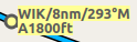
VOR or NDB range rings labeled with ident and frequency. Color indicates Navaid type. This feature can be added from the map context menu using Add Navaid Range Ring. |
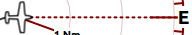
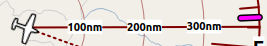
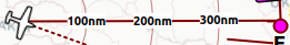
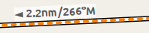
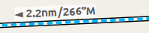
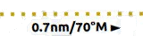
|
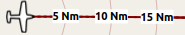
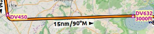
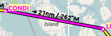
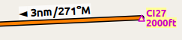
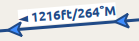
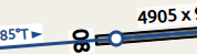
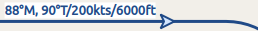
Great
circle
distance and course measurement
line indicating length and true
heading at start and destination.
The two heading values will be
equal for small distances. For
shorter distances length is also
shown in feet or meter.
The width of distance measurement
lines can be changed in the
dialog |
|
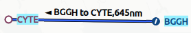
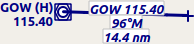
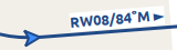
Measurement lines starting from an airport or navaid have the same color and additional ident and frequency labels. Course will consider calibrated magnetic declination of a navaid. This feature can be added from the map context menu using Measure Distance from here. |
|
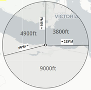
MSA diagram to scale. Right click on a MSA symbol and select Add MSA Diagram to show this. See Minimum Sector Altitude for more information. |


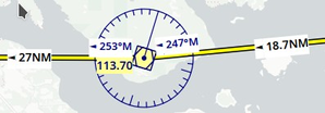
13.6. Compass Rose
Line thickness can be changed in dialog Options on the tabs
Map Display User and Map Display Labels.
The colors for flight plan leg course and heading indicator depend on
settings for active flight plan leg which can be changed in the dialog
Options on tab Map.
Symbol |
Description |
|---|---|
|
True north. |
|
Magnetic north. |
|
Distance circles and marks from user aircraft if connected. |
|
Solid line shows aircraft track in degrees magnetic if connected. |
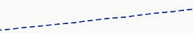
|
Dashed line shows aircraft heading if connected. |
|
Magenta line segment shows the course to next waypoint of the active flight plan leg. Hidden if no flight plan loaded. |
|
Heading indicator. Shows the heading that has to be flown towards the next waypoint of the active flight plan leg considering cross wind. Hidden if no flight plan loaded. |


13.7. Aircraft and Ships
Labels for the user and AI aircraft can be configured Options on the tab Map Display Labels.
Display of traffic can be enabled or disabled in menu View Menu.
Symbol |
Description |
|---|---|
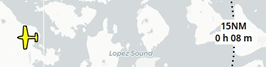
|
Current user vehicle if connected to the flight simulator. The user aircraft depends on selected aircraft (jet, piston/turboprop or helicopter). |
|
User aircraft on ground or ship. |
|
Aircraft carrier and frigate (X-Plane only) |
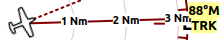
|
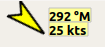
Needle showing the current ground
track of the aircraft. Aircraft
nose shows heading. Can be disabled in |
|
Selected altitude range arc.
Position where the selected autopilot altitude will be reached.
This display can be disabled in menu |
|
Aircraft turn flight path line. This predicts the flight path.
This display can be disabled in menu |
|
Aircraft endurance with distance and hours:minutes to go. This uses reserve fuel,
contingency fuel, current fuel flow, fuel on
board and ground speed to calculate the endurance
This display can be disabled in menu |
|
User aircraft trail.
Display can be toggled in menu |
|
Wind around the user aircraft with direction in degrees magnetic and speed. |
|
AI or multiplayer aircraft.
Labels vary and can be customized
in |
|
Dark red color indicates online network aircraft/client. Labels vary and can be customized as above. |


13.8. Airports
Airports having control towers are shown in dark blue others in magenta. Add-on airport names and idents are shown italic and underlined throughout the whole program. Airports that are part of the flight plan have a light yellow text background.
The symbol is shown smaller if an airport has no runways. This is the case for some add-on airports that use another techniques like photo scenery to display runways.
Labels and diagram elements for airports can be configured Options on the tab Map Display Labels.
Display of airports can be enabled or disabled in menu View -> Airports.
Symbol |
Description |
|---|---|
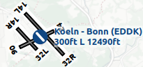
|
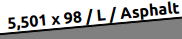
Airports with hard surface runways longer than 8,000 ft or 2,400 m. All runways longer than 4,000 ft or about 1,200 m are shown. Only for lower zoom distances. |
|
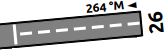
Airports with hard surface runways. White line shows heading of longest runway. |
|
Airports with soft surface runways. |
|
Empty airports shown in gray. No taxiways, no parking spots and no aprons. |
|
Seaplane base having only water runways. |
|
Military airport. |
|
Heliport having only helipads and no runways. |
|
Abandoned airport. All runways are closed. |
|
Airports that have fuel available. |
|
Add-on airports are always
highlighted.
You can disable this in
the options dialog on page
Map Display by unchecking
|
|
Weather at airport. See chapter Airport Weather below. |
|
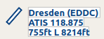
Airport label showing name,
ident, ATIS frequency, elevation,
lighted runways ( |
|
Airport runway overview shown before the full airport diagram when zooming in. |


13.9. Airport Diagram
Runway, taxiway, helipad and apron colors indicate surface type. White is used for an unknown or invalid surface type given by an add-on developer.
Diagram elements for can be enabled or disabled in Options on the tab Map Display Labels.
Symbol |
Description |
|---|---|
|
Runway with length, width, light
indicator ( |
|
Runway end with ident and magnetic heading. |
|
Displaced threshold. Do not use for landing. |
|
Overrun area. Do not use for taxi, takeoff or landing. |
|
Blast pad. Do not use for taxi, takeoff or landing. |
|
Taxiway with name and center line. |
|
Closed taxiway. |
|
Semi transparent dotted aprons and taxiways indicate that no surface is drawn. It might use a photo texture or simply the default background. |
|
Tower. Red if a tower frequency is available. Otherwise just view position. |
|
Fuel |
|
GA ramp with parking number and heading tick mark. |
|
Gate with number and heading tick mark. Second ring indicates availability of jetway. |
|
Cargo ramp |
|
Military combat parking or cargo ramp. |
|
Helipads. Red text indicates medical helipad. Color indicates surface. |


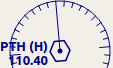
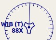
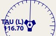
13.10. Navaids
Navaids that are part of the flight plan have a light yellow text background.
Display of navaids can be enabled or disabled in menu View -> Navaids.
Symbol |
Description |
|---|---|
|
VOR DME including ident, type and frequency. Compass rose shows magnetic declination on lower zoom distances. Small blue rectangle at high zoom levels. The type defines the reception range:
|
|
VOR including ident, type and frequency. Tiny blue rectangle at high zoom levels. |
|
DME including ident, type and frequency. Small blue rectangle at high zoom levels. |
|
TACAN including ident, type (High, Low or Terminal) and channel. Compass rose shows magnetic declination on lower zoom distances. Small blue rectangle at high zoom levels. |
|
VORTAC including ident, type (High, Low or Terminal) and frequency. Compass rose shows magnetic declination on lower zoom distances. Small blue rectangle at high zoom levels. |
|
NDB including ident, type and frequency.
Small dark red circle at high
zoom levels.
The type defines the reception range:
|
|
Waypoint with name. Small magenta triangle at high zoom levels. |
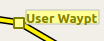
|
User defined flight plan waypoint with name. |
|
Invalid airport, waypoint, VOR or NDB that is part of the flight plan but could not be found in the Scenery Database. |
|
Marker with type and heading indicated by lens shape. |
|
Jet airway with label showing name, type (Jet or Both), minimum and maximum altitude. Text depends on zoom distance. A preceding arrow will show the allowed direction if the airway is one-way. |
|
Victor airway with label showing name, type (Victor or Both), minimum and maximum altitude. Text depends on zoom distance. A preceding arrow will show the allowed direction if the airway is one-way. |
|
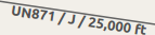
Eastbound PACOTS track with
flying direction, name |
|
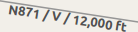
Westbound PACOTS track with
flying direction, name |
|
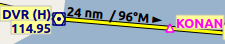
ILS with glideslope and markers. Label shows ident, frequency, magnetic heading, glideslope pitch and DME indication if available. |
|
Localizer. Label shows ident, frequency, magnetic heading and DME indication if available. |
|
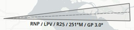
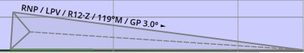
GLS/RNP approach glidepath indicating a precision approach.
Can be disabled in menu |
|
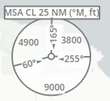
MSA symbol (minimum sector altitude). Can be attached to an
airport, a runway or other navaids.
Right click on this symbol to add a diagram which is to scale.
Labels shows |
|
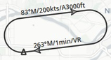
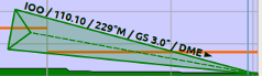
En-route holding. Labels are outbound course, speed and altitude. Inbound label shows inbound magnetic course, leg time and navaid name. |


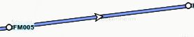
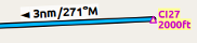
13.11. Flight Plan
Flight plan display labels can be changed in dialog Options on
tab Map Display Labels. Look can be changed on Options page Map Display Flight Plan.
See also Flight Planning.
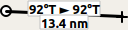
|
Flight plan with distance,
direction and magnetic course at
each leg.
|
|
Blue fixed course labels show inbound and outbound course for VOR also depending on the calibrated declination. Blue indicates VOR inbound and outbound course with VOR calibrated declination. Otherwise black. See Magnetic Declination for more information on flight plan course and magnetic declination. |
|
Flight plan procedure leg with the same information as above. |
|
Active flight plan leg. |
|
Wind direction and speed at flight plan waypoint. See chapter Winds Aloft below for details about wind barbs. |
|
Flight plan departure position on airport. Either parking, fuel box, helipad, water or runway. |
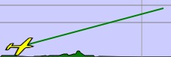
|
Top of climb point with distance
from departure.
Can be disabled in menu |
|
Top of descent point with
distance to destination.
Can be disabled in menu |


13.12. Procedures
See chapter Procedures and Search Procedures for more detailed information on all the legs.
The ellipsis … indicates that additional information, such as altitude restrictions
is available, which is not visible due to the zoom factor. Zoom in closer to see the details.
Symbol |
Description |
|---|---|
|
SID, STAR, approach or transition leg for flight plan and in preview with distance, direction and magnetic course at each leg. |
|
Missed approach leg for flight plan and preview. |
|
Dotted line indicates circle-to-land or straight-in part of a procedure leading to a runway end. Here part of flight plan. |
|
Vector leg indicating course to an initial fix. Here part of flight plan. |
|
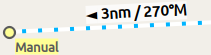
Manual leg. Fly according to ATC instructions. Here shown as preview. |
|
Leg to alternate destination. |
|
Gray yellow filled circle indicates a procedure point which is not a navaid but defined by course and/or distance from a navaid, an altitude restriction or manual termination. |
|
A black circle indicates an overfly waypoint. Can be a procedure point or a navaid. |
|
The Maltese cross highlights the final approach fix or the final approach course fix. |
|
Prefix |
|
Fly a heading, track or a hold until manually terminated by ATC. |
|
Intercept the next approach leg at a course of about 45 degrees. |
|
Procedure leg that is terminated when reaching the given altitude. |
|
A fix defined by a course or heading and distance to a navaid. |
|
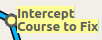
Turn to intercept a radio navaid radial. |
|
This fix is defined by a heading or track which is terminated by reaching a DME distance. |
|
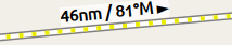
Intercept a course to the next fix at an angle of about 45 degrees. |


13.13. Elevation Profile
The colors and symbols of the elevation profile follow the style of the main map as set in the options dialog on tab Map Display. Colors, patterns and symbols for airports, navaids, procedures, active and passed flight plan legs are the same. The profile display also follows other map settings like visibility of flight plan line, aircraft and aircraft trail.
See also Elevation Profile Display Options for customization options.
See Elevation Profile for more information.
Symbol |
Description |
|---|---|
|
Ground with departure elevation on the left and destination airport elevation on the right. |
|
Flight plan altitude. |
|
Top of climb with distance from departure. |
|
Top of descent with distance to destination. |
|
At altitude restriction of a procedure with waypoint name. |
|
At or above altitude restriction of a procedure. |
|
At or below altitude restriction of a procedure. |
|
At or above and at or below (between) altitude restriction of a procedure. |
|
Minimum safe altitude for flight
plan. This is elevation plus 1,000
ft rounded up to the next 500
ft. The 1,000 ft buffer can be
changed in the dialog |
|
Minimum safe altitude for a flight plan segment. The same rules apply as to the minimum safe altitude for flight plan. |
|
User aircraft if connected to the simulator. Labels show actual altitude and climb/sink rate. |
|
User aircraft trail if connected to the flight simulator. |
|
Projected vertical path by current climb or sink rate |
|
ILS slope. Label shows ident, frequency, magnetic heading, glideslope pitch and DME indication if available. Only shown if an approach is selected and runway end has an ILS. Opening angle has no relation to actual slope precision. |
|
GLS/RNP approach path indicating a
precision approach.
Can be disabled in
menu |
|
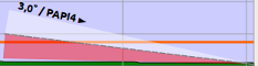
Visual Approach Slope Indicator. Label shows slope pitch and VASI type. Only shown if an approach is selected and runway end has a VASI. Opening angle has no relation to actual slope precision. |
|
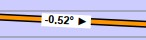
Calculated vertical descent path angle during the descent phase. |
|
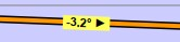
Required vertical descent path angle in a procedure. This is a procedure restriction. |


13.14. Airport Traffic Pattern
Color and indicators depend on user choice in Traffic Patterns dialog.
This feature can be added from the map context menu using Add Traffic Pattern.
Symbol |
Description |
|---|---|
|
Downwind leg of airport traffic pattern with altitude and magnetic course. |
|
Final leg of airport traffic pattern with runway and magnetic course. |
|
Arrow and dashed line shows path for pattern entry. |
|
Dashed line and arrows show path for pattern exit. |
|
White circle is active point at the runway threshold of the pattern. Mouse cursor changes above and allows to remove the pattern in the context menu. |


13.15. Holding
Color depends on user choice in Holdings dialog.
This feature can be added from the map context menu using Add Holding.
Symbol |
Description |
|---|---|
|
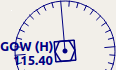
Holding fix, magnetic and true
inbound course, time for straight
leg and navaid ident ( |
|
Magnetic and true outbound course, speed and altitude as given in the dialog. True course display depends on options. |
|
Active point and holding fix. Mouse cursor changes above and allows to remove the holding in the context menu. |


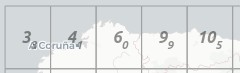
13.16. MORA Grid
The minimum off-route altitude grid provides an obstacle clearance altitude within an one degree grid. The altitudes clear all terrain and obstructions by 1,000 ft in areas where the highest elevations are 5,000 ft MSL or lower. Where the highest elevations are above 5,000 ft MSL terrain is cleared by 2,000 ft.
Display of the MORA grid can be toggled in menu View -> Show Minimum off-route Altitude Grid.
Symbol |
Description |
|---|---|
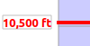
|
MORA grid. Large number is 1,000 ft and small number 100 ft. Example here: 3,300, 4,400, 6,000, 9,900 and 10,500 ft. |
13.17. Airport Weather
Display of airport weather symbols can be toggled in menu View -> Show Airport Weather.
The weather source can be selected in menu Weather -> Airport Weather Source.
See also Weather.
13.17.1. Flight Rules
Symbol Color |
Description |
|---|---|
|
VFR. Visual flight rules. |
|
MVFR. Marginal VFR. Visibility equal or below 5 statue miles or lowest ceiling at or below 3,000 ft. |
|
IFR. Instrument flight rules. Visibility below 3 statue miles or lowest ceiling below 1,000 ft. |
|
LIFR. Limited IFR. Visibility below 1 statue miles or lowest ceiling below 500 ft. |


13.17.2. Cloud Cover
Symbol |
Description |
|---|---|
|
No clouds. |
|
Few |
|
Scattered |
|
Broken ceiling |
|
Overcast |


13.17.3. Wind
The source for winds aloft forecasts can be selected in menu Weather -> Wind source.
See also Winds Aloft.
Symbol |
Description |
|---|---|
|
No pointer indicates wind below 2 knots. |
|
Pointer without wind barb shows wind below 5 knots from north-west. |
|
Short barb is 5 knots wind. |
|
Long barb is 10 knots wind. |
|
50 knots wind. |
|
Example: 25 knots. |
|
Example: 65 knots. |
|
Example: 15 knots steady wind (black) gusting to 30 knots (red). |


13.18. Winds Aloft
Symbol |
Description |
|---|---|
|
No pointer indicates wind below 2 knots. |
|
Below 5 knots from west. |
|
Example: 25 knots. |


