23.  Elevation Profile
This dock window shows the ground elevation, flight plan with cruise, climb, descent legs and altitude restrictions together with all flight plan waypoints. It is only available when a valid flight plan is loaded. The user aircraft will be shown if Little Navmap is connected to the simulator.
The elevation profile does not cover missed approaches and legs to alternate airports. Create a new flight plan from the destination to the alternate airport if you wish to use the elevation profile.
Movement of the aircraft and the trail in the elevation profile is tied to the active flight plan leg and will not be correct if flying away from the active leg.
Note
The elevation display covers only the flight plan and will not change the depiction if you get off the flight plan with your simulator aircraft. You need a valid flight plan (i.e. a departure and destination airport) and a valid aircraft performance file to see the elevation profile.
23.1. Top Label
Following information is shown in the top label if connected to a flight simulator with a valid flight plan:
Distance from user aircraft to flight plan destination
Estimated time en-route in hours and minutes
Distance from user aircraft to the top of descent
Estimated time to top of descent in hours and minutes
Example: Destination: 47 NM (0 h 28 m). Top of Descent: 26 NM (0 h 15 m).
The label is hidden if not connected to a simulator.
23.2. Tooltip Label
Additional information is shown in a tooltip label at the right or left side in the window if the mouse is hovered over the diagram. The corresponding position is highlighted on the map with a black/cyan circle. The label changes the side depending on mouse position.
The label shows the following information for the mouse position:
Distance from departure and to destination plus calculated altitude and next waypoint.
Coursefor the flight plan leg at the cursor position.Headingfor this flight plan leg at the position. This is calculated based on wind conditions and omitted if it is the same as course.The
Flight path angleis only shown in the descent phase and shows the vertical angle. The label changes toRequired flight path angleif a descent path is reqired by a procedure.Groundaltitude and calculated altitude above ground.Leg safe altitudeof the flight plan leg at the cursor position (orange line).Winddirection and speed as well as head- (▼) or tailwind (▲) component.
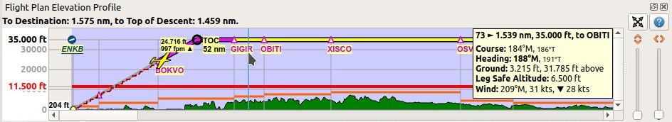
Information for position between waypoints GIGIR and OBITI.
Indicating a headwind of 28 kts at this position.
User aircraft still climbing.
Note the image showing German number format with dot as thousands separator.
23.3. Zoom Sliders
The right side of the elevation profile contains the zoom sliders. The following controls are available:

Splitter: You can resize the right part of the elevation profile window using this splitter button. The part containing the sliders will be collapsed if you drag it to the far right. You can open the collapsed part again by dragging the splitter to the left. The look of the splitter might be different on another operating system.
Expand to Window: Resets the view back to 100 percent showing the whole flight plan.
Display Options: See Elevation Profile Display Options.
Help: Opens this online help page.
Zoom Vertically: Move the slider up to zoom in vertically. Maximum zoom results in 500 ft height for the whole profile window.
Zoom Horizontally: Move the slider up to zoom in horizontally. Maximum zoom results in about 4 NM distance for the whole profile window.
23.4. Mouse Movement
Hover: The corresponding position within the flight plan is highlighted on the map with a black/cyan circle.
Wheel: Zoom in and out horizontally.Shift+Wheel: Zoom in and out vertically.Left Click and drag: Move map up, down, left or right.Left Double Click: Zoom to position on main map.Right Click: Show context menu.
23.5. Keyboard Movement
Click on the elevation profile window to activate it before using the keyboard.
Cursor keys: Move map up, down, left or right.
+and-: Also on numpad. Zoom in and out horizontally.*and/: Also on numpad. Zoom in and out vertically.0orIns: Reset view to 100 percent and show the whole flight plan.HomeandEnd: Jump to departure or destination.PageUpandPageDown: Move forward or backward one page.
23.6. Elevation Profile Display Options
Choose Elevation Profile Display Options from the elevation profile context
menu to customize labels and other display features.
The dialog uses a tree. See Trees for more information about this type of input element.
Same as main menu Tools -> Elevation Profile Display Options.
23.7. Context Menu Elevation Profile
23.7.1.  Show Position on Map
Zooms to the corresponding position on the map. This is the same as double clicking into the elevation profile.
23.7.2. Expand to Window
Resets the view back to 100 percent showing the whole flight plan.
23.7.3.  Keep User Aircraft Centered
If this option is selected, the aircraft remains centered on the left of the altitude profile during flight.
The aircraft will be kept on the upper part of the window if the aircraft is descending and on the lower part if climbing. You can move around the profile manually. After a time without manual movements it will jump back to the aircraft.
The vertical and horizontal zoom distances set by the user are not changed while Little Navmap keeps the aircraft visible.
See also for more information on jump back in the options dialog on Simulator Aircraft which partially affects this function. See the related tooltips for more information.
This function is independent of the related Keep User Aircraft Centered.
23.7.4.  Center on Aircraft and Destination
Same as Keep User Aircraft Centered above but additionally zooms the elevation profile to keep aircraft and destination visible when checked. This hides the unneeded passed flight plan legs.
The vertical and horizontal zoom distances set by the user are not changed while Little Navmap keeps the aircraft visible until the destination is visible on the right side of the map. The elevation profile starts to zoom in horizontally and vertically as much as possible to keep the destination and the user aircraft visible then.
The function Keep User Aircraft Centered has to be enabled to use this function.
Note that the elevation profile starts zooming fairly late after at least half of the flown flight distance.
23.7.5.  Delete Aircraft Trail
The aircraft trail is saved and will be reloaded on program startup.
This menu item removes the user aircraft trail from the elevation profile only. It does not remove the trail from the map. Use this if the trail appears in the wrong place or shape after creating of modifying a flight plan.
The trail in the elevation profile is of no relevance for the GPX file export.
23.7.6.  Show VASI
Shows a VASI slope if an approach procedure with a runway (not circle-to-land) is selected in the flight plan and if the runway has a VASI.
The slope is drawn with the correct angle to be usable as an approach guide. The vertical opening angle is only meant for depiction and has no relation to the real VASI accuracy.
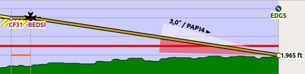
Display of VASI slope at destination airport. Slope is 3 degrees and VASI type is PAPI4. Final approach fix is marked with a Maltese cross.
23.7.7.  Show ILS or GLS/RNP
Shows an ILS glideslope or GLS/RNP approach paths if an approach with a runway is selected in the flight plan and if the runway has the related navaid or approach type.
Drawing of approach guidance depends on selected approach procedure type. An ILS approach will show the ILS feathers while a localizer approach without vertical guidance will not. Note that no vertical navaid guidance is shown for circle-to-land approaches.
The slope is drawn with the correct angle to be usable as an approach guide. The vertical opening angle is only meant for depiction and has no relation to the real ILS accuracy.
A label on top shows name, frequency, heading, glideslope angle and DME indicator if available
Note
The ILS glideslope and GLS/RNP glidepaths can be forced to display for all approach types:
Disable ILS or GLS/RNP on the toolbar or in the menu
View-> Navaids to see only flight plan related navaids on the map and approach related navaids in the elevation profile. This means you won’t see an ILS glideslope for a VOR approach in the elevation profile, for example.Enable ILS or GLS/RNP to see slopes in the elevation profile independent of the approach type. A destination runway ( Select Destination Runway) or an approach ( Search Procedures) has to be selected to see the slope.
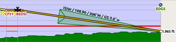
Display of ILS at destination airport. Final approach fix is marked with a Maltese cross.
23.7.8.  Show Top of Climb and Top of Descent
Hides the climb and descent slopes as well as the top of climb and top of descent indicators when disabled. This affects the map and elevation profile display but not the altitude calculation in the fuel report or elevation profile.
This is the same function as Show Top of Climb and Top of Descent in the menu View.
23.7.9.  Show Vertical Track
Shows a vertical track line indicating the flight path based on current descent or climb rate as well as ground speed.
Use this to aim at the right altitude at the next flight plan waypoint. This is especially useful at descent.
Related function for the map is Show Selected Altitude Range Arc in the map context menu.
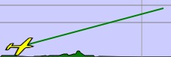
Vertical track line in elevation profile window indicating climb rate.
23.7.10. Follow on Map
The map view will be centered - not zoomed in - on the position below the cursor if hovering above the elevation profile when this option is selected.
23.7.11. Show Zoom Sliders
Show or hide the zoom sliders and buttons at the right side of the elevation profile. You can still zoom using the mouse or the keyboard.
23.7.12. Show Scrollbars
Show or hide the scroll bars at the bottom and the right side of the elevation profile. You can still use the mouse or keyboard to navigate.
23.7.12.1. Elevation Profile Display Options
See Elevation Profile Display Options above.
23.8. Profile Display
The colors, symbols and font of the elevation profile follow the style of the main map as set in the options dialog. Colors, patterns and symbols for airports, navaids, procedures, active and passed flight plan legs are the same. The profile display also follows other map settings like visibility of flight plan line, aircraft and aircraft trail.
Display options for the flight plan can be changed in Map Display Flight Plan. Not all of the flight plan options affect the elevation profile which is noted in the related tooltips.
Aircraft heading will turn if a backward movement relative to the active flight plan leg is detected.
For more information see the Elevation Profile in the map legend.
The elevation profile uses actual altitude for display of restrictions, slope and cruise.
The aircraft icon is shown using indicated altitude to ensure matching to cruise altitude line at the higher flight levels.
You might see vertical aircraft movement of the aircraft symbol and jumps in the trail when adjusting barometric pressure in the simulator altimeter.
Note
Keep in mind that actual altitude shown in Little Navmap might differ from indicated altitude even with a correct baro setting.
This is an effect of the outside air temperature (OAT) on actual altitude where low temperatures affect the aircraft altimeter. When temperature is less than ISA conditions an aircraft will be lower than the altimeter reading.
This effect is currently modeled in X-Plane 12 and MSFS.
Corrections have to be applied when the aerodrome temperature is 0°C or colder:
DH/DA or MDH/MDA and step-down fixes inside the final approach fix (FAF).
All low altitude approach procedure altitudes in mountainous regions (terrain of 3000 ft AMSL or higher)
See SKYbrary - Altimeter Temperature Error Correction for more information.
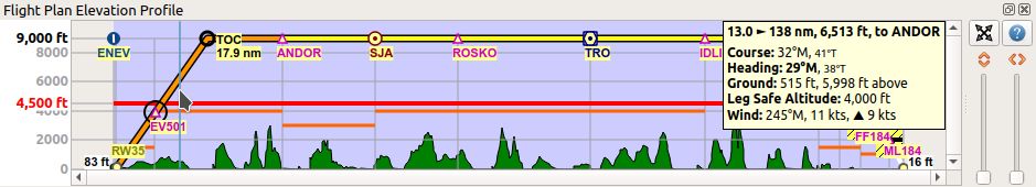
Flight plan elevation profile with line indicating
the mouse hovering position. Orange lines show minimum safe altitude for
flight plan segments. Red line shows overall minimum safe altitude. Top
of climb and top of descent points shown including slope. Orange flight
plan lines show procedure legs. Waypoint EV501 has an overfly
condition and there are several altitude restrictions shown for the
approach procedure below the tooltip.
23.9. Top of Climb and Top of Descent Paths
The elevation profile also displays the top of climb and top of descent which are calculated based on the current Aircraft Performance profile and Winds Aloft situation.
Note that the TOC and TOD calculation is influenced by altitude restrictions in procedures. Little Navmap will calculate a climb or descent path always adhering to these restrictions. The resulting path might use a higher or lower climb or descent speed than expected.
The path is also forced to the lowest allowed altitude at the final
approach fix (FAF) and the final approach course fix (FACF) to avoid arriving above
the ILS glide slope or too high at the destination runway.
You can safely follow the descent path as shown by Little Navmap, provided you can manage your aircraft speed at the same time. For large aircraft you might want to descent around 10 nm earlier to reduce speed to 250 knots below 10,000 ft.
I recommend to make the descent path manually more shallow (i.e. use a lower sink rate) to take the deceleration phases into account.
The climb and descent paths are affected by wind and are moved accordingly for strong head- or tailwinds. The climb path will be steeper in the elevation profile if you climb in a strong headwind, for example.
See chapter Winds Aloft for more information.
The plan will switch to a flat display showing only a flight plan line at cruise altitude if the TOC and/or TOD cannot be calculated or if the plan violates altitude restrictions. A red warning message is shown in the Error Messages Footer on the flight plan tab if this is the case. Click the message for more information.
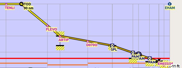
An approach procedure which requires the aircraft to descent early due to a restriction between 7,000 and 10,000 ft at ARTIP.
23.10. Elevation Data
Elevation processing is done in the background since online data has to be downloaded and computation is CPU intensive. Therefore, the update of the elevation display can take from a few seconds up to half a minute. This background update is started after creating or changing the flight plan or when new elevation data was downloaded. The display will be updated accordingly whenever new data is available.
23.10.1. Online Elevation Data
Note that the third party online elevation data does not cover all countries and currently ends at 60 degrees north. The data contains several known errors which cannot be fixed.
The calculation of online elevation points is limited to flight plan segments not longer than 2,000 NM to avoid overloading. Add more waypoints or calculate a flight plan to avoid this limitation.
23.10.2. Offline Elevation Data
Using the recommended freely downloadable GLOBE - Global Land One-km Base Elevation Project elevation data has several advantages:
Faster updates
World wide coverage
No known errors
Display of altitude below the cursor in the status bar
Correct altitude if using non-airport departure and destination points
Resolution is a bit lower than the one for the online data, though.
See Install GLOBE elevation data in the options dialog for instructions how to download and install the GLOBE elevation data.